¶ Goggle X variants
Since release there have been various changes made to the Goggles X
- Oct 2023: Original release goggle - Tin heat spreader
- Jan 2024: Version to address overheating - Black heat sink
- Jan/Feb 2024: Version to address overheating and ‘orange’ channel bars - Short black heat sink
- Sept/Oct 2024: Version to address lack of head tracking - Short black heat sink, Built-in 9axis head tracking gyro, improved analogue input support
- Jan 2025: Latest version - Short black heat sink, Built-in 9axis head tracking gyro, improved analogue input support, Different RAM
Thanks to Nuno Pinho
¶ Proximity Sensor Disable
If you cannot see the menu to be able to disable the proximity sensor, you can still do so using the following process.
1. Power off VTX as this will interfere with the following process steps.
2. Power on the goggles and wait for bootup
Short press the 5D Button in the following sequence.
Down(press) - Right - Right - Down(press) - Down(press) - Left - Down(press) - Forward - Down(press)
3. Done
See a video of the process Here
¶ Live Streaming
How to live stream your video feed from the Goggles X (and the V1) using OBS Studio
See HERE for details.
Goggles X Blackscreen - Booting problem - Signal reception problems: Troubleshooting guide by Vítězslav Částka
As all of us know, the QC of Goggles X has been a problem and the hardware is so sensitive to any little detail, that it stops working or damages itself.
¶ Display Malfunction
Symptoms:
Mostly the right eye display is known to be problematic and stops working. It falls into black screen or changes contrast, or show strange stripes.
Cause of the problem:
The cause of this problem is overheating of display and it’s driving electronics.
Solution:
Replacing the original heatsink on the motherboard with the new one that Caddx will provide you for free if you send them e-mail to service@caddxfpv.com, or see here
¶ Explanation:
It seems like nonsense that better cooling of the motherboard will help cooling display’s electronics, but there is more to the heatsink than just more aluminium and more fins that helps dissipate the heat. The new heatsink also provides a channel for the air to travel, directing the hot air from the CPU outside the ventilation hole on the cover. It seems like that was always the way it should have been because the channel for the heatsink is prepared on the plastic lid. Maybe if people weren’t spamming and crying about how “long” it takes Caddx to release the goggles, it would be released without these problems.
¶ Booting Problem
Symptoms:
Goggles won’t boot up at all or at 10th time.
Software hanging at random intervals (sometimes it could work without problems for up to several minutes).
Cause of the problem:
- Messy thermal paste on places where it shouldn’t be. Probability: 90%
- Something bad with SD Card. Probability: 9%
- Defective motherboard and has to be replaced by Caddx: 1%
Solution:
- Be really careful and precise during the heatsink change and preferably use thermal pads than the blue thermal paste that is used and provided to you by Caddx. More info about the details of the change in How to change Goggles X Heatsink.
- Simply use a working Class 10 card or no card.
- Send your question to service@caddxfpv.com .
¶ Explanation:
- The motherboard is badly designed and there are many things that can cause problems with the CPU and ROM memory reading. If there is excessive amount of thermal paste and it gets between really small contacts on ICs anywhere on the motherboard, it can create unwanted capacitance on that place that could filter some high frequency signals going through traces MB or can create a resonance circuit and provide a noise that could not be filtered. Also the routing of coaxial cables for main antennas and even the wifi antenna can provide a noise to onboard ICs that are prone to it, because they are poorly shielded. All antennas should be far as possible from any IC. More details in ‘How to change Goggles X Heatsink’ section below.
- Goggles are searching for files on SD card during the startup for example the file that unlocks channels and it can get stuck when there are damaged sectors on the SD card.
¶ Signal reception problems
Symptoms:
All channels are “red” and the stability and bitrate during flight is bad.
Cause of the problem:
Mangled coaxial cables for the antennas or even disconnected IPEX during assembly.
Solution:
Check if the antenna cables aren’t squeezed under the heatsink or anywhere else.
¶ Proximity to RC link transmitter.
Symptoms:
Goggles locking up or rebooting.
Cause of the problem:
Putting goggles near to your radio transmitter. This is an issue that has been demonstrated primarily with 868/915mhz RC links to varying degrees on all the major vendor HD goggles, however there are some reports of it happening with the 2.4ghz band too.
Solution:
Keep some separation between your RC radio and your goggles.
¶ Analog Module Addition
Something you can add to the Goggles X is an analog module. Unfortunately the analog video is usable only from firmware version 37.42.7 otherwise there are some problems with brightness and contrast of the video.
The slickest way to make the module tray is to remove the unnecessary long module pins and solder everything directly to the module. At the end you can have something that is not destroing the footprint of the goggles at all.
There are some versions in developement:
- Analog Module Holder For Goggles X by Vincentpartman - Thingiverse
This variant is easier and does not need full disassembly of the goggles, but a cooling fan will be good to add.
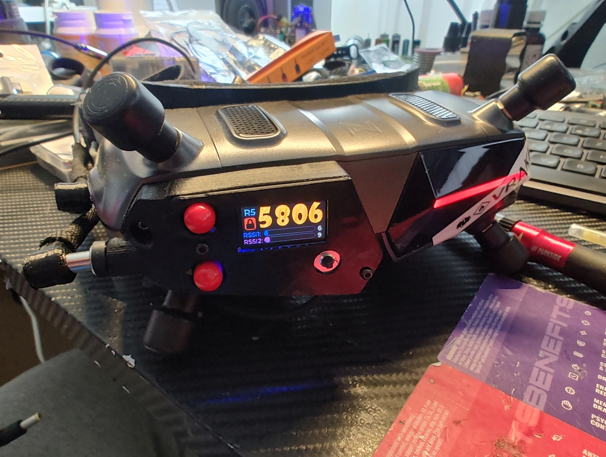
- Caddx Walksnail Goggle X analog mod with DVR by KhangNguyenFpv - Thingiverse
Remixed variant that contains even a DVR and is made to connect everything right inside the Goggles X power port. This needs complete disassembly of the goggles but it is much finer design.
¶ How To Change Goggles X Heatsink (The precise way)
Things you need:
- Phillips head screwdriver
- Knife
- Something for Prying - damaged propellers are great for that.
- Thermal pads (Could be bought on Aliexpress in a set of many thicknesses)
- 0,5 mm thick
- 1,0 mm thick
- 1,5 mm thick
- Thermal paste – Optional
- Isopropyl alcohol
Change of the heatsink:
1. Unmount the faceplate.
2. Unscrew the two screws under the faceplate.
3. Pry off the plastic cover carefully. Prying of the plastic cover should be done without excessive force and with as much upward direction as possible, because the mounting holes for screws can damage parts on boards and most probably the IPEX of the Wifi antenna.
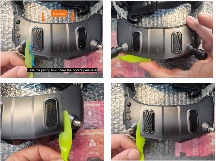
4. Unmount the cover upwards and be careful, because there is an antenna mounted on the cover from the inside. (I am doing it for third time just for this tutorial, so there is already new heatsink)
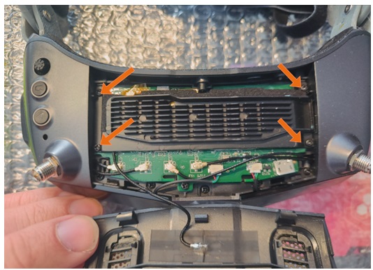
5. Unscrew 4 screws that are holding the heatsink. It is recommended to unscrew it in cross pattern.
6. Take off the heatsink. (Here is a photo how it looked like under original heatsink. This was pair of Goggles that worked perfectly even with the original heatsink.
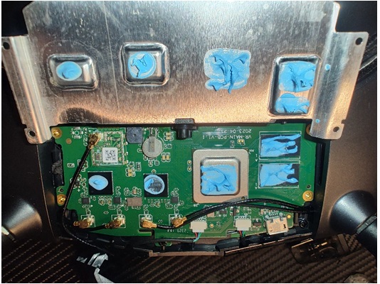
7. Disconnect the WiFi antenna IPEX and put the cover aside.
8. Clean the PCB from the thermal paste with the cleaning alcohol. And look for details. The thermal paste can be everywhere. Even under the integrated circuits.
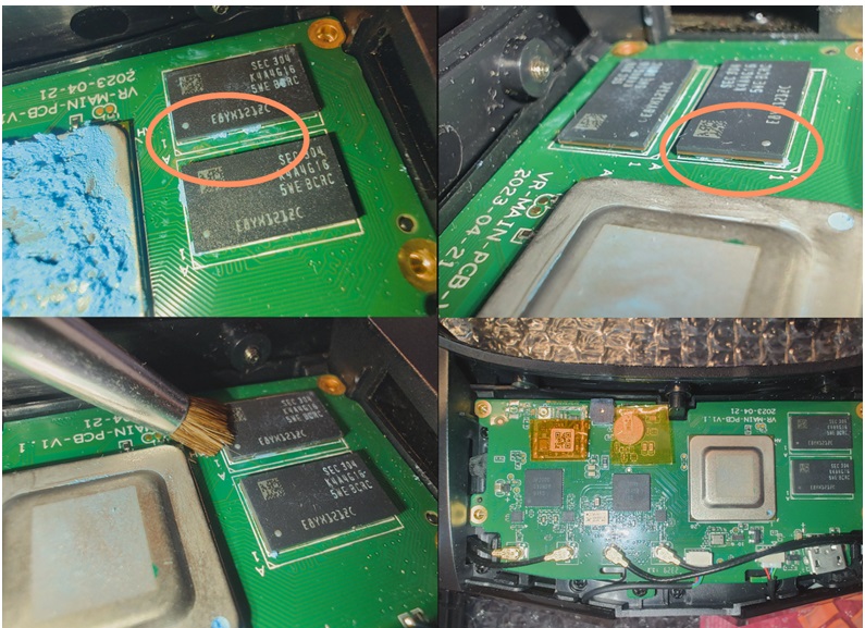
9. After everything is cleaned up, you should put a kapton tape on the cmos battery and also the wifi module. A small piece of kapton tape will be used to cover the wifi antenna as well.
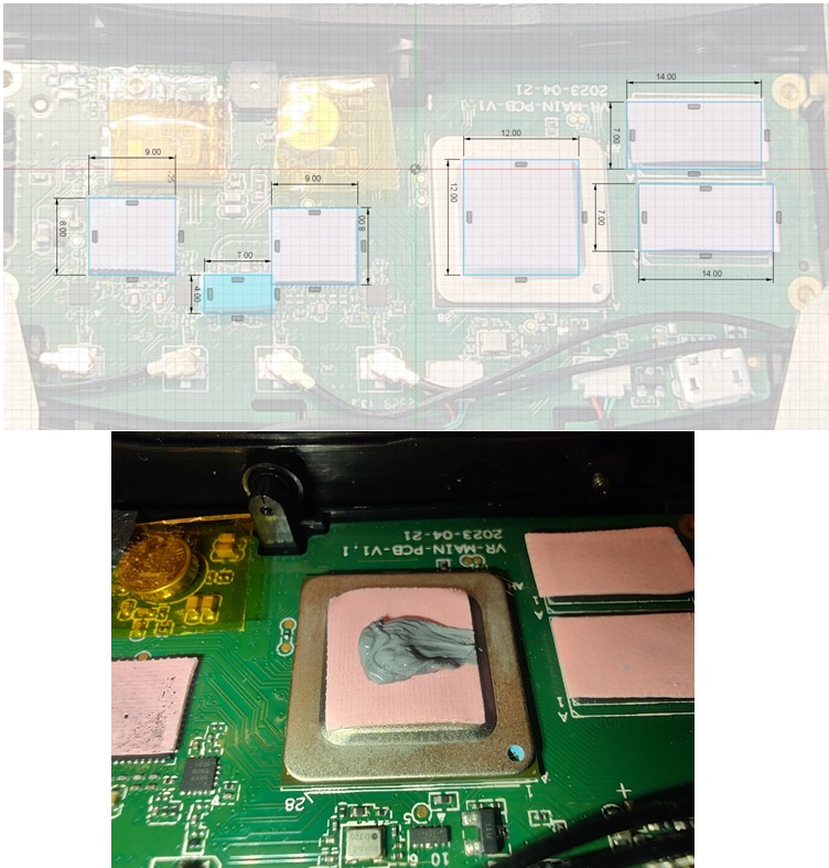
10. Now is the time to put the right sized thermal pads on the right places. Pink thermal pad is 0,5 mm, the green one is 1,5 mm. You can use a 1,0 mm thermal pad on the CPU but It can cause the heatsink to bend and not be well seated on the other components, so I prefer to fill the rest (0,1mm probably) with thermal paste just on the CPU.
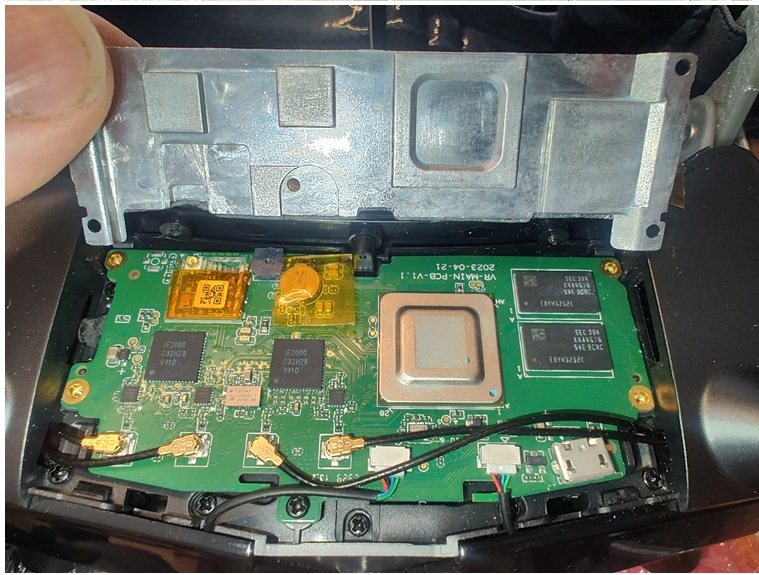
11. Route the antenna coaxial cables in a way that it won’t get squeezed under the heatsink.
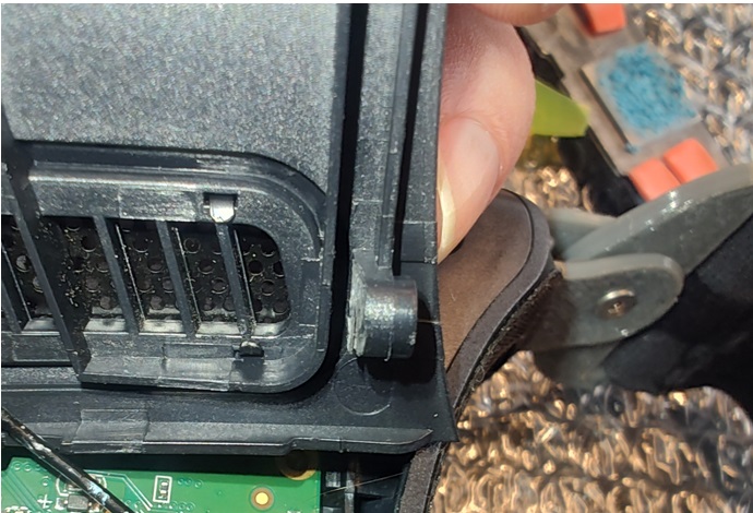
12. Cut off a small part of the mounting screw holes so it won’t crash into the motherboard during assembly.
13. Connect the wifi antenna and route it around the left side, not in the middle of those two ICs.
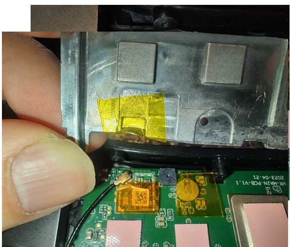
14. Add a kapton tape onto the IPEX connector of the wifi antenna or on the heatsink at the place that is over the connector.
15. Put the heatsink on the PCB and screw it with cross pattern.
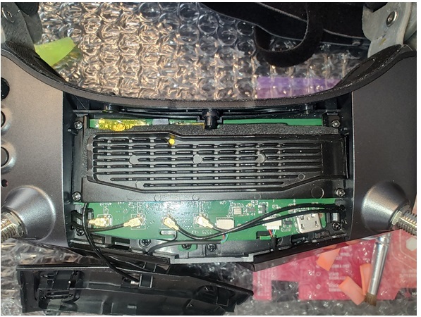
16. Now the wifi antenna coaxial cable needs to be slightly tangled up, so it won’t get on the heatsink or under it. It should be just over the antennas IPEX connectors.
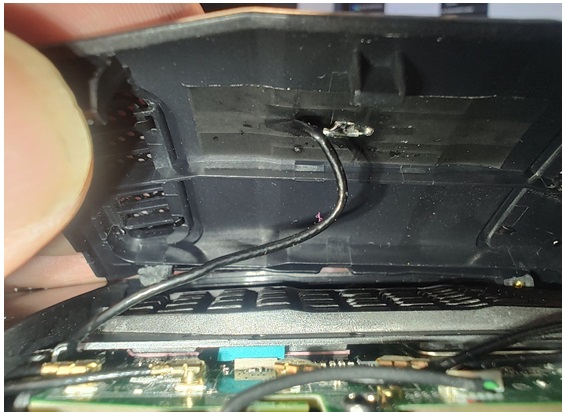
17. You can close the cover now and screw in those two mounting screws from the faceplate side.
Results:
If everything is done right, here is the result.
The before state on thermal camera looked like this:
You can see, that the hotspots are all over the goggles and above the right eye.
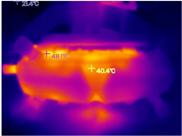
The state after the heatsink upgrade is as follows:
This photo is taken after around 30 minutes of full operation with ambient temperature of 25°C.
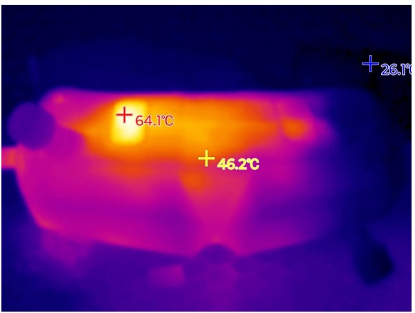
Don’t be scared of the heat that is coming from the grille. It surely is a grill. But important thing is that the goggles are taking the heat out finally. The maximum temperature in the 25°C ambient temperature that you can see in the debug screen in the goggles should be from 68 to 70 °C and there it should stop. Here you can see the sped up 30 minutes testing video:
¶ GoggleX Unbricking Procedure (similar process for V1 and VRX)
Thanks to oZak
*This procedure is not for the faint hearted. It is very risky and should only be completed as an absolute last resort. The authors take no responsibility if you damage your goggles beyond repair*
Things you need:
-Thin and very flexible wires (be aware, thick wires can make the test points break ->tested without intention of it)
-USB OTG cable ( unpowered, yes there are powered ones, I cannot confirm, but with powered ones you shall not need to jump the diode as I have heard from others )
-USB to TTL converter at 3.3V(check otherwise it might damage the unit)
-USB 2.0 Flash Drive, formatted to FAT32
-A pair of Tweezers
-Plastic Pry Tool ( could use old bent props, bent, not broken with sharp cutting edges )
THIS disassembly video may also prove useful
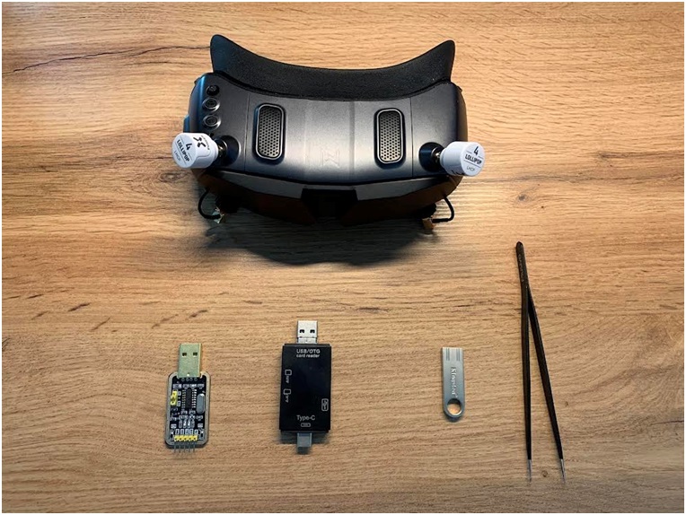
-Open the goggles by undoing the 2 screws after taking off the mask.
-Use the plastic Pry Tool to remove the top plate:
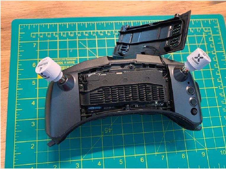
-Unscrew the 4 screws for the heatsink and remove it. Disconnect the 4 antenna connectors and wifi antenna:
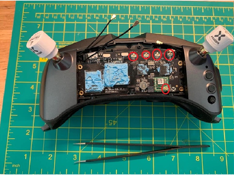
-Lift up the VRX board slowly so you can undo the Ribbon Cable and the MIPI (Power & Controls ??) connector . After undoing remove the board. To better work on it further you can put again the heatsink over it, the putty shall keep it in place:
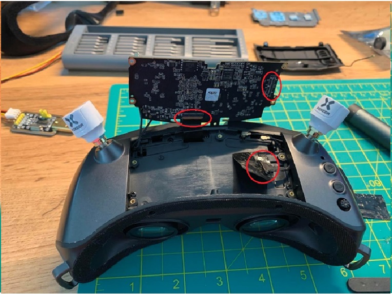
-Solder the wires to RX,TX and GND on the VRX board. Solder a wire to the terminals of the Diode to make a jumper, do not desolder it if you do not have the tools:
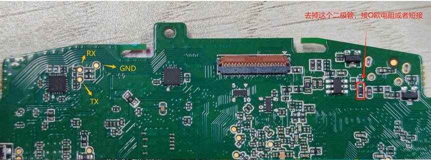
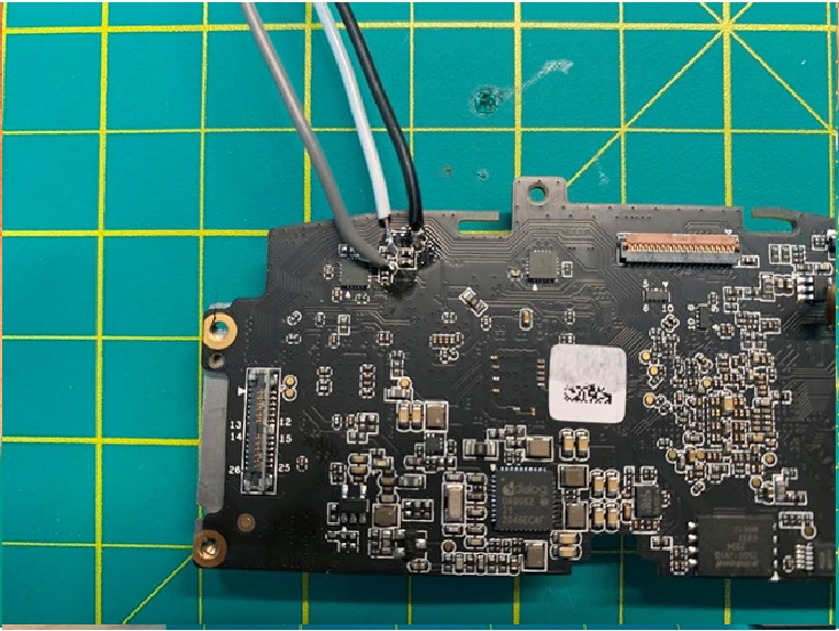
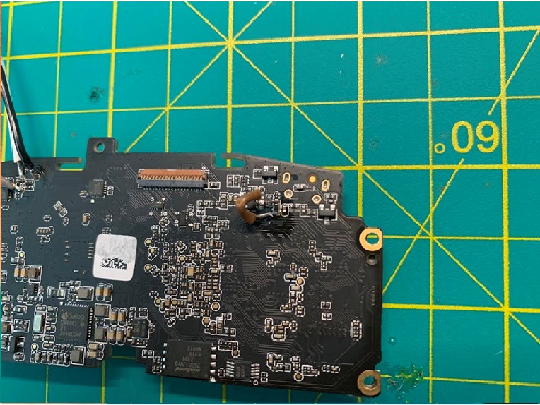
Ignore thick wires used in the photos, you need VERY THIN wire to avoid stripping of the Test Point !!!
The other end of the wires should be connected to the USB to TTL converter as follows:
VRX GND -> Converter GND
VRX TX -> Converter RX
VRX RX -> Converter TX
¶ The Flashing Process
-Take the firmware you want to flash from HERE, rename it to “walksnail-upgrade-sirius-0.0.0.1.img” and copy it to the USB 2.0 Flash on your PC/laptop.
-Download a Serial Port Communication software such as TeraTerm. Set Baudrate to 115200, XON/XOFF disabled.
-Connect the VRX Ribbon and Mipi cable again.
-Connect the USB Flash 2.0 drive using the OTG cable to the micro USB port on the VRX.
-Connect the USB top TTL converter to your PC.
-Connect to the new serial session on Serial Port Communication software and leave the console open for you will need to type letter ‘u’ while booting.
-After connecting the battery or the PSU and the Goggles X bootup you will have info dumped on the serial window, while this is happening press ‘u’ and keep it pressed until it enters update state (it will prompt update segments and a lot of data location etc).
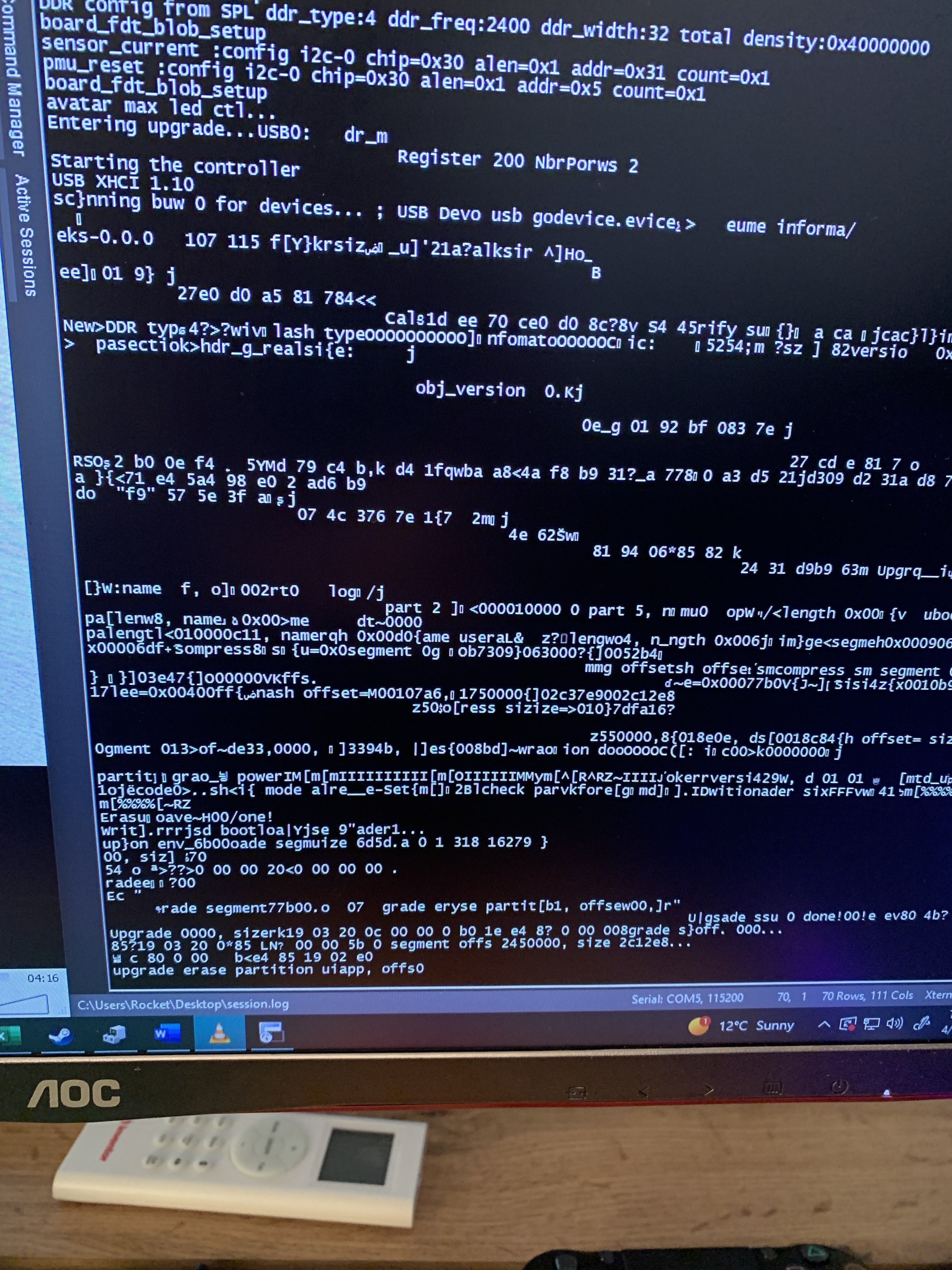
-After aprox 5 min or less you will be prompted on the serial console to reboot the board. When that happens do a powercycle and that should be it.
¶ Original CADDX support info
To complete the process, you will need a usb OTG unit, a usb flash drive and a usb to TTL device. The usb to TTL needs to have 3V3 logic levels exactly to not damage the board, so this needs to be measured on the converter used. The usb OTG need to be 2.0 with the flash drive formatted toFAT32.
-Remove the VRX unit from the Goggles X. check a Goggles X disassembly guide for this step HERE. BE VERY CAREFUL!
-Remove the diode in the picture and replacing it with a 0 ohm resistor or short circuit it (the purpose is to power the U disk). Connect usb to OTG cable to the usb port on the VRX. to connect the U disk.
-Connect the usb to TTL device to the VRX uart pads
ZIP FILE of info provided by Caddx